TaPRK
General
Projects
Shows
Excursions
Links
Yleistä
Ratoja
Projektit
Näyttelyt
Retket
Linkit
Parish/SRK
Tapiola Parish Model Railway ClubProjects: Signals ... |
|---|
Photos on this page are courtesy Opa, Antti, Olli and Pekka
- OP_4.ASM
- Orignal code, comments and variable names in finnish
- OP_4_eng_B.asm
- Translated to English to aid following the code (updated in 2022-04-17).
- kelt.gif
- The 8 bit module. The unused pins of RJ-connector are used for power transmission (filtered 5 volts). The pins are chosen so that each signal becomes twisted with one of the power feeders and as the power consumpton of modules is low this is hoped to reduce transmission errors.
|
|
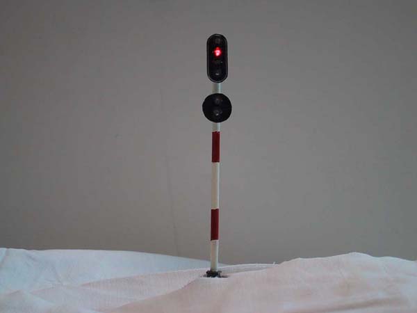
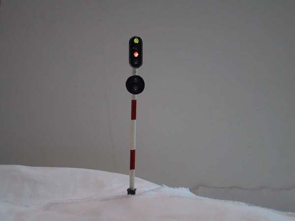
Olli has made some semaphores. In the upper image is a four-light home signal and a two-light distant signal in the same mast. The home signal is displaying a "Stop"-signal. In the lower image is the same signal mast, but displaying a "Proceed 35 km/h"-signal. The distant signal should be displaying a "Except Proceed 35 km/h" or "Except Stop"-signal, but anybody knows why it isn't... |
Signalling logic, slow motion light signals
The Stations have colour light starter signals operating in slow motion. The small station and the other end of large station (there are no names yet!) have all analogue slow motion setup.
The small staton has limited CMOS logic "interlocking": one can get only one starter at each end green at the same time and only one home signal may be green at one time. The light change slowly and like the real thing the red light dimms out and only after it has goen out completely will the green light brighten up. The home signals are not yet fitted as we have not yet resolved the best way to fit them to modules (the home signal could be at any module).
Signal mastheads (for DIY-signals):
The other end of the big station has the same features, but they are microcontroller driven. A PIC16F84 processor operates three starters, home signal and distant home according to points settings. All the signal's LEDs will go on and off slowly. This is done with PWM incorporated within the PIC. The signals are operated with three position toggle: in mid-position all are red, if turned outward the correct starter will show green and if turned inward the home signal will show green. the correct starter is picked from turnout position feedback. There is a provision for a single train detector to sense the area between starters and home (the pointwork and part of the line) and in case a train is found there it will automatically put all signals to red. the control switch must be reset in order to get next green.
The assembler code was coded using finnish variable names and all comments are in finnish. I'm trying to get the code "translated" into english, but this may take some time. The beginnings are found below:
Signal masts are to be fitted to modules close to stations or at locations where block signalling is needed. The layout is provided with "sockets" or "foundations" for signals:
Due to modular design the signal mast foundations are needed at every module. Hence the foundations have been designed to be simple to make and install (just a 5 cm length of 10mm outer dia. 8 mm inner dia. water pipe.
Serial transmission of data between control panel and layout
We have also played with the idea of getting less wires between control panel and layout. We have looked into serial transmission. Below is a link to our proto module schematic.A time base module is to be connected between layout modules and control panel modules. It will generate the timing pulses and cross connect the data in and data out lines and count the clock pulses needed between strobe pulses:
This setup has not been tested in "real life" and still a project under development! [Actually project cancelled]
8786 kävijää/visitors
© 1996-2023 Tapiola Parish Model Railway Club / Tapiolan seurakunnan pienoisrautatiekerho, Viimeksi päivitetty / last modified (none). Created with Notepad.
Text, drawings and photos are protected by copyright laws. Technical solutions, methods and source code are public domain only for non commercial purpose. All development has been carried out during our free time, mainly funded from our own pocket and with non selfish goals, so the use of this material for profitable use (including construction for a friend aginst a fee) is forbidden without written permit from the club. The pages contain errors, so, if you use the data given, you do so at your own risk and responsibility. If you further develop material found on these pages you must put it on display without fee e.g. to a freely available web page. We expect a note about this also.
Pages tested with W3C validator -- didn't look good ;)
[YHTEYSTIEDOT] Älä lähetä sähköpostia!
Tekstit, kuvat ja piirokset ovat tekijänoikeuslain suojaamia. Tekniset ratkaisut, menetelmät ja lähdekoodit ovat vapaasti kopioitavissa ja hyödynnettävissä ei-kaupallisissa tarkoituksissa. Kaikki kehitystyö on tehty vapaa-aikana ja pääosin henkilökohtaisilla varoilla eikä hyötymistarkoituksessa, siksi materiaalin käyttö hyötymistarkoituksiin (sisältäen kaverille rahasta rakentamisen!) on kielletty ilman kerhon kirjallista lupaa! Sivuilla esiintyy virheitä. Jos käytät sivujen tietoja hyväksesi, teet sen täysin omalla vastuullasi. Mikäli kehität sivuilla esiettyjä ajatuksia kytkentäkaavioita tai koodia edelleen, on sinun asetettava se maksutta kaikkien saataville esimerkiksi Internetiin. Odotamme vastavuoroisesti tietoa suoritetusta edelleenkehitystyöstä.
Sivut testattu W3C validatorilla -- ei näyttänyt hyvältä ;)