Fast response input?
I needed fast response, (for the CTC-panel). I used the joystick fire-button
connection. One could trap that (with MSX-BASIC) to generate an interrupt
and read the buttons of the panel, and beep. The real time loop then handled
the actions later, thus the operator got the feeling of instant response,
and the feel of huge CTC-system!
This system was originally designed for Helsinki Club's Pihlajamaa layout's
computerized power box (signal box) in 1987. I recently found the original MSX-Basic
software, and converted it into
PDF. Some special characters are not displayed
and the end of the software appears to be missing.
As the Pihlajamaa layout was sold before the computerized power box was finished I took the
unfinished C/MRI setup to Tapiola to be used as Computerized Cab Control system.
Usually Computerized Cab Control is connected to layout with relays, that
connect the desired cab to desired section. In case of three controllers
usually two relays are needed per section.
At Tapiola a different approach was "invented": All cabs had their own
relay banks and each of them were divided into "odd" and "even" blocks of relays.
If the loco is on "odd" section of track, no power is travelling through
the "even" relays, and they can change state. As the train enters to "even"
section, no power travels through the "odd" relays, and they can change state.
A loco will only need two sections to be powered at one time, provided we know
the direction the the loco is travelling, or if lineside signals are so set that
the loco has no way of travelling to unpowered section.
An example:
As the loco was under control of cab A and was on an even block, the
odd bank of cab A's relays could connect the power to the next or previous
block. This way only two blocks could be connected to a same cab, but that
is enough!
The layout had 13 blocks and 3 cabs and only needed 19 relays (3 cabs:
8 even and 8 odd blocks (3 relays each). The one extra relay took care
of handling the power routing while going from block 13 (odd) to block
1 (odd). NB: No saving in relay count will be gained, if the number of
blocks and/or controllers/cabs is small. The pictures show a situation were the excact
number of relays needed is the same, but if the system is larger, the
relay count comes down nicely.
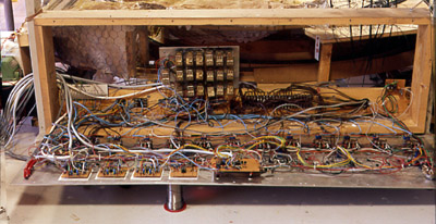
Picture of the inside of the CTC-panel, the relays are in the middle
Forwarding
If a train is standing in a station with power applied. The computer
knows that this is to be connected to engineer A. If the points were thrown,
the train becomes isolated and the detector looses the train. Now the computer
switches off the power, but puts the cab code in memory if the engine becomes
detectable again.
Train leaving the station
If we are to forward this train from the station, we must first set
the points to that siding. The detector notices the train and computer
switches power to the rotary section. If we then give the train a permission
to proceed say, from section 6 to section 7, the power of cab
A is applied to section 6 (as detector picked up the loco) and to section 7
if starter signal is cleared.
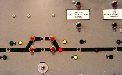
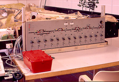
The CTC-panel showing a train about to depart from siding (Yellow LED
next to turnout detotes that it's thown, red LED in the track diagram
denotes that the train detector has sensed the train, and green LED
inside signal symbol is lit to show that the train may proceed. the black
buttons top right are group buttons used in conjunction with the switch
immediately below the station area. If a train is to be forwarded, the switch
below station area is thrown to the direction of intended travel
and black group button ("Kulkutien varmistus") "create route" is pressed.
if the route need s to be canselled, the group buttom
"kulkutien hätäpurku" ("emergency delete route") is pressed. In case
the train crew needs to do shunting within station area the group buttons
"paikallisluvan anto ("grant local control") and "paikallisluvan palutus"
("delete local control") will be used. This will provide power to both ends
of the station area blocks irrespective of train detectors.
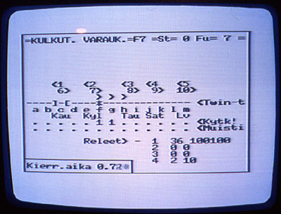
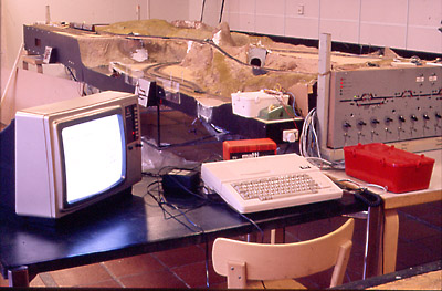
The same situation on screen: due to lack of space the rotary sections are
coded with letters instead of numbers. The line (with text "Twin-T") has a star
where a train is detected. immediately above the star there are arrows at
blocks 6, 7 and 8 (f, g and h) denoting that the computer is giving permission
for the train to proceed to the right from these sections. The row marked
with text "Kytk!" ("conn!") denotes which cab is connected to this section. We see that
the cab/controller 1 (or A) is connected to sections 6 and 7 (f and g). The row
marked "Muisti" ("Memory") displays the throttle numbers that are taken in to memory
in case two locos occupy same block (but the one in memory has been made dead
by throwing points!). The kind of tunnel shown on screen at block 3 (c) means
that the turnouts are so set, that a train travelling from block 2 (b) will
travel directly to block 4 (d), and not through the block 3, which is the goods
yard. The numbers with arrows above the track line are denoting which of the
computer's function keys would create route. By pressing the space bar one could
toggle between four group buttons, and the text at the top of the screen showed
which of the group buttons was activated (this was used before the control panel
got the buttons). the area marked as "releet" (relays) displayed the status of the four
output ports. the state was displayed in decimal and binary form. The "Kierr.aika"
("loop time") shows the real time loop time (this version has quite a lot of
code in assembler, the plain basic version had reatime loop times well above
2 seconds!
As the train proceeds it will appear in section
7 and later dissappear from section 6. The computer knows that trains don't
dissapear, but move from one section to another, so if due to bad contact
the train should dissappear while about to move to section 7 no false actions
will be made. Only as the train is completely within section 7 will the
section 6 be released. If the section 6 would be the destination of the train,
the dissapearing of the train is considered as the train being isolated
by throwing the points -- the section will be de-energised and the cab
code will be put into section 6 memory. If this was an intermediate section
and not the destination, as is now the case the dissappearance of the
train will not de-energize the secton.
Train meet
If another train is to enter the station occupied by a train, the standing
train must be made dead by throwing the turnouts to a free siding. Now the cab number
of the standing train dissappearing from detection is put into memory and the
section may now be assigned to the cab of the approaching train.
If this train is accidentally loosing contact, the cab cannot be put into memory
as there is already another cab code there!
Only after the train has completely left the rotary section that the standing
loco occupies, may we re-energize the standin loco by throwing the points.
Now the loco will get the cab assignded by the code in memory.
Passing a train
Passing another train works similarily, but if there is no actual feedback
of the turnout position, and two trains are standing at the station, both facing the
same direction, the train last entered to the staion must leave first. Only if turnout
feedback is provided the the throwing of the points could be interpreted as a command
to swap the cab number in memory to that in use and vice versa.
Tapiola had only six turnouts with feedback to computer, as at these instances the
turnout position caused the train to enter different section. This was shown with
"tunnel" symbols on screen.
Latest all-basic version of the software TaPRK_C-MRI_v1.11.zip
Latest found version of the software TaPRK_C-MRI_v2.8.zip
13 train detectors were needed, and they were connected so that, while
using power routing turnouts, they lost sight of the train as the points
made the track or section dead.
But as the computer knew that the points were thrown it thus knew where
the loco was. The detectors were a sort of mixed design of diode version
of Twin-T and Mudies detector (described in 1970's in MR). (Again, I throught
that Dr Chubb's design of Optimized detector was not optimized moneywise, I'd rather
have four detectors with the price (and component count) of one of his ;).
The schematic and picture of the power part of detector
The actual detection part consisted of anti-parallel diodes and
antiparallel transistor base-emitter junctions. The collectors were tied together
and formed a open collector output with no delay. A 33 nF capacitor was need
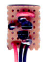
to smoothen out erroros. This diode+transistor unit was assembled on a thumbnail
size vero board, inserted into plastic film container and connected underneath
the layout. the open collector lines were taken to the control panel for
delay and amplification. This made the heavy duty wiring shorter too.
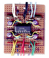
The schematic of delay/amplification unit and picture of the quad delay/amplifier
The amplification consisted of 1/4 LM324 op-amp, 1 uF / 3.3 Mohm three seconds off delay and
instant on and sensitivity trimmer.
Post Mortem
With PC you could get all the info through a Centronics port, and at around 10 dollars
a piece it is not a great investment even though you would blow one. Unfortunately
todays computers running under Windows have no longer direct connection to LPT port,
so one must either make a bootable diskette and load old fashioned DOS software there
with the operating system, or resort to commercial software, but those are nicely
tied to only commercial hardware so the DIY programmers are really having hard times!
19837 kävijää/visitors
© 1996-2023 Tapiola Parish Model Railway Club / Tapiolan seurakunnan pienoisrautatiekerho,
Viimeksi päivitetty / last modified (none). Created with Notepad.
[CONTACT INFO] Don't send e-mail!
Text, drawings and photos are protected by copyright laws. Technical
solutions, methods and source code are public domain only for non commercial
purpose.
All development has been carried out during our free time, mainly funded
from our own pocket and with non selfish goals, so the use of this material
for profitable use (including construction for a friend aginst a fee) is forbidden
without written permit from the club. The pages contain errors, so, if you
use the data given, you do so at your own risk and responsibility. If you
further develop material found on these pages you must put it on
display without fee e.g. to a freely available web page. We expect a
note about this also.
Pages tested with W3C validator -- didn't look good ;)
[YHTEYSTIEDOT] Älä lähetä sähköpostia!
Tekstit, kuvat ja piirokset ovat tekijänoikeuslain suojaamia.
Tekniset ratkaisut, menetelmät ja lähdekoodit ovat vapaasti kopioitavissa
ja hyödynnettävissä ei-kaupallisissa tarkoituksissa. Kaikki kehitystyö on
tehty vapaa-aikana ja pääosin henkilökohtaisilla varoilla eikä hyötymistarkoituksessa,
siksi materiaalin käyttö hyötymistarkoituksiin (sisältäen kaverille rahasta
rakentamisen!) on kielletty ilman kerhon kirjallista lupaa! Sivuilla esiintyy
virheitä. Jos käytät sivujen tietoja hyväksesi, teet sen täysin omalla vastuullasi.
Mikäli kehität sivuilla esiettyjä ajatuksia kytkentäkaavioita tai koodia
edelleen, on sinun asetettava se maksutta kaikkien saataville esimerkiksi Internetiin.
Odotamme vastavuoroisesti tietoa suoritetusta edelleenkehitystyöstä.
Sivut testattu W3C validatorilla -- ei näyttänyt hyvältä ;)
|
![Address and data clock [2K]](/img/general/cmri_addr1.gif)
![Address latch [2K]](/img/general/cmri_addr2.gif)
![Address decoding [3K]](/img/general/cmri_addr3.gif)
![Address data sep, address latch, input driver [XK]](/img/general/cmri_main.jpg)
![Output board [32K]](/img/general/cmri_o.jpg)
![Input board [27K]](/img/general/cmri_i.jpg)
![The whole lot (cmri)[XK]](/img/general/cmri_all.jpg)